The Blohm & Voss Bergahorn
The planes illustrated here are all fictional, though their backstory is tightly interwoven with fact. The historical background and engineering principles are based solidly on fact, as are the cast of characters, though their actions may not all be. It is for the interested reader to ferret out the historical truth and divide it from invention, but be warned, the weave is tight.
Through the latter part of WWII the Blohm & Voss Advanced Design office, under Chief Designer Richard Vogt and his Head of Advanced Design Hans Amtmann, turned out a great many weird and wonderful designs. If you wanted an asymmetric jet flying boat, they had one for you! Besides the immediacies of war, their eyes were also turning to the future of civil aviation and, increasingly, the landplane successors to the long-distance flying boats they had always specialised in.
One oddity which I stumbled on in 2018 is their Projekt 225 "Bergahorn" (Sycamore). Documentation, as ever with these projects, is scrappy but I have been able to piece together several fragmentary references to build a partial picture.
Projekt 225 was one of several studies aimed at developing a very large aircraft capable of flying long distances. This one was particularly inspired by the idea of flying über den Wetter, above the weather. Whether it would be an Amerikabomber or an airliner was undecided, and both avenues were initially pursued. The airliner study was designated P 225 and the reconnaissance/bomber P 226. Confusingly, both were sometimes referred to together as the P 225. Their traditional flying boat solution was, wisely, rejected in both cases as unsuited to efficient high-speed, high-altitude über den Wetter flight. But even a conventional landplane would struggle to meet the demands of the future; instead the flying wing was attractive due to its high inherent efficiency, with the payload carried in the wing. Trim considerations required that the payload be held in only the forward part of the wing, so the total wing area would be generous and the loading relatively low. This gave it inherent high-altitude capability. This in turn suited it to jet propulsion, which should also confer high speed at such altitudes.
P 225.01
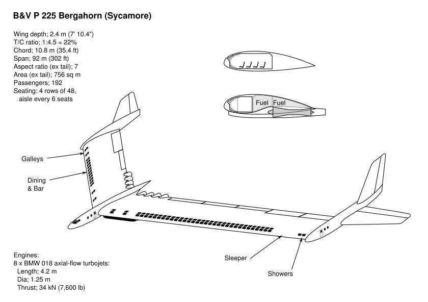
The only viable structural solution for such a passenger-carrying wing is to make the entire cabin a torsion box so it doubles as the main spar. Fortunately this kind of torsion-spar construction was Vogt's trademark feature, though he usually used it for fuel tankage rather than passengers. However, to get adequate headroom meant an aerofoil over 2 m (6 ft 7 in) thick. The speed benefit of high altitude was thought to make a relatively squat aerofoil viable provided it was not heavily loaded, nevertheless it would have to have a chord of at least 10 m (33 ft). The problem was, that to give an adequate aspect ratio for efficient flight, initial studies suggested a wingspan of around 250 m (820 ft)!
The first refinement was to adopt the swept, outboard-tail design they were developing for a jet fighter. A characteristic of this arrangement is a lift and structural force distribution which favours a constant-chord wing, offering maximum payload for minimum span. Moreover it does not need long, tapering and empty tip sections, instead having short booms and tail planes. This reduced overall span to around 110 m (360 ft), better but still oversize for the design payload of 200 passengers.
The engines and fuel were grouped together in the centre section and the passengers housed outboard of them. This both provided some crash survivability and minimised trim changes in the event of engine failure. It is interesting to note that this is a reversal of the modern habit, to put the passengers in the middle and the engines and fuel outboard. It is also an improvement, as there is no need for a huge tail fin to meet the engine-out condition.
With his experience of asymmetric design, Amtmann realised that he could discard much of one wing, further reducing the wingspan, cost and engine power required. One side was therefore drastically shortened, the penalty being a vertical fin added after all, to balance the torque of the asymmetric engine thrust. The appearance of the result immediately earned all subsequent variants the name Bergahorn, after the asymmetric winged seed of the Sycamore tree.
A subtle interplay between the various control surfaces was devised, so that any odd effects of asymmetry were overcome. For example the centreline runs through the innermost landing flap of the long wing and the asymmetries in both lift and drag cancel out when all four surfaces are deployed.
Eight BMW 018 turbojets of 34 kn (7,700 lb) thrust apiece, having already been under development for several years, would provide sufficient thrust and their intake ducts were run underneath the connecting corridor. The entire rear halves of the central fuselage nacelle and wing centre sections housed the fuel, conveniently located alongside the centre of lift to minimise pitch trim changes during flight. However lateral trim would need to be progressively adjusted. One suggestion was that the dining room and bar would remain closed for the first two hours of flight, until the tanks on that side had emptied a bit!
These were still the days of luxury air travel, so sleeper cabins and even a couple of showers were provided, as far away from the engines as possible.
I don't know if the undercarriage was ever finalised. One scheme had an extendable leg in the short wing boom, radar-controlled to maintain the same height above ground as the other wheel. Another had the outermost wheel brought inboard until it aligned. I'll let you know if I find out more.
The drawing shows a composite impression made up from the records available to me, with a little educated guesswork to fill in the gaps.
Skoda-Kauba SK.B7
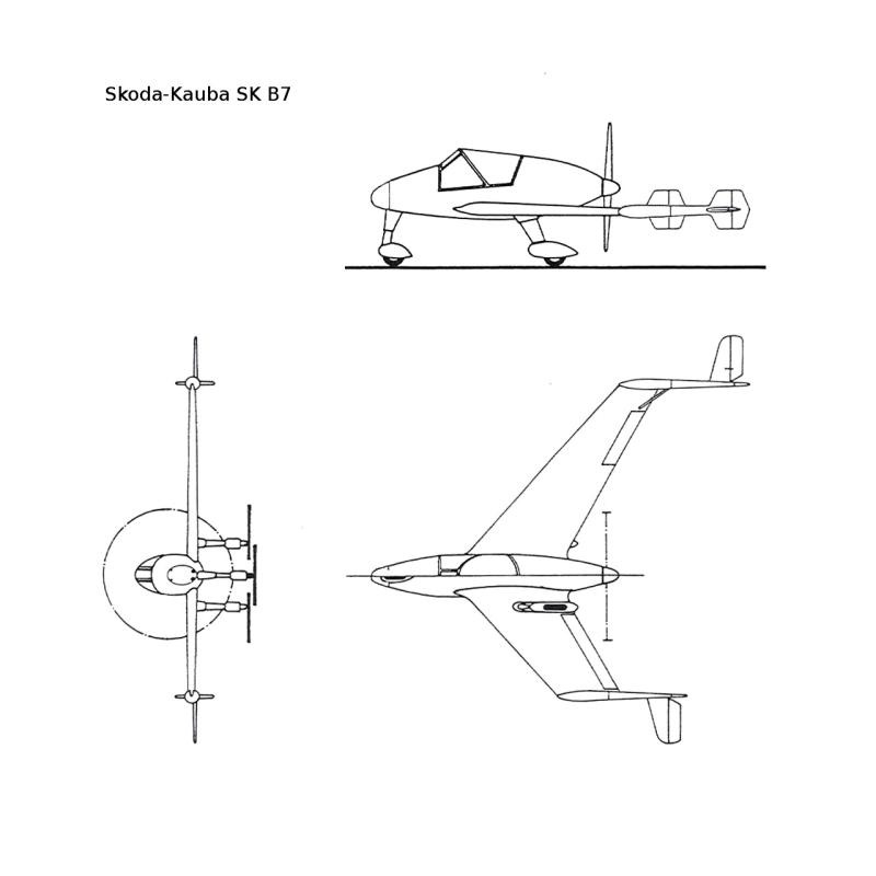
As with the radical control system of the original outboard-tail design, the P 208, B&V wanted to test out the even more unconventional control system for the Bergahorn. And coincidentally just as before, Otto Kauba had a suitable prototype available. This time it was his S7, a swept-wing pusher type with canard foreplane that the RLM had lost interest in before it had even flown. Skoda-Kauba removed the whole nose section and foreplane assembly, hacked one wing down and installed the tailbooms, complete with outboard tails, from the old SL6. They also re-used the SL6 nose, faired in with a new adapter section.
The reinvented machine, redesignated the SK B7 (for Bergahorn 7), certainly proved the need for careful balancing of the various anomalies introduced by the asymmetry. A series of short but eventful flight trials and subsequent modifications eventually produced an arrangement which the test pilot described as "barely flyable" and, with sufficient data now gathered, the test programme was ended.
The drawing shown is not very accurate, but does give the general idea. It depicts the original form of the B7, before the tail fins and rudders were redesigned.
P 225.02
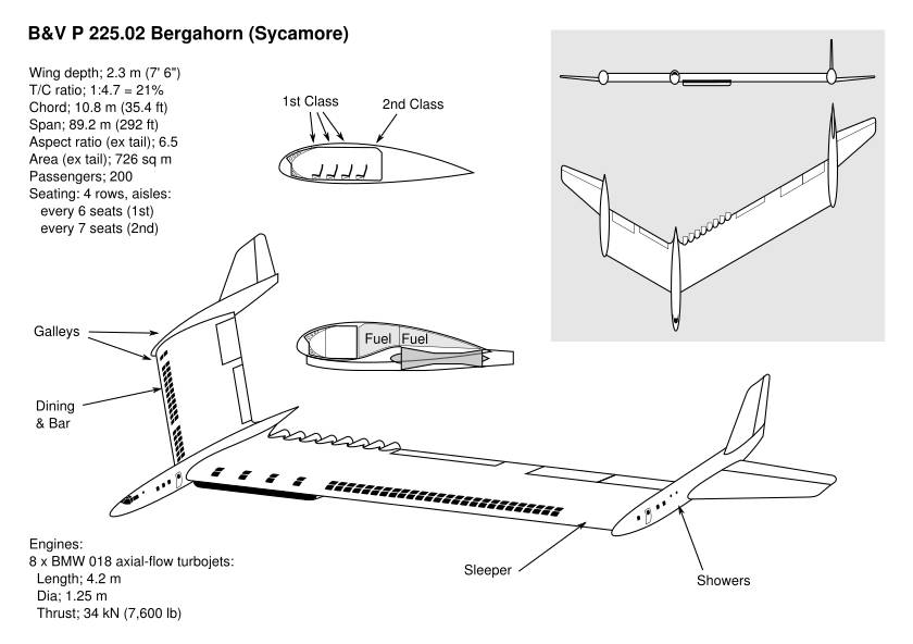
Barely flyable is, of course, not good enough. The P 225.02 was developed to overcome this and other issues that were emerging.
The undercarriage problem was proving unyielding. Amtmann returned to the solution used on the BV 144 prototypes, of a variable-pitch wing to avoid the need for major fuselage pitch changes during takeoff and landing. Careful curvature of the wing end bulkheads and adjacent nacelle sides avoided any clash of surfaces during rotation, while a fail-safe system of electrical and hydraulic linkages synchronised pitch adjustment at all three nacelles.
During his attempts to overcome the undercarriage problem, Amtmann had also realised he had blundered in leaving the engines on either side of the main nacelle. He moved them to one side of the nacelle, nearer the aerodynamic centre. This allowed a major reduction in fin area and its associated weight and drag penalties. The presence of the forward nacelle meant that it could not be wholly eliminated.
Ingenious redesign of the main cabin, including recessed panel fixings, re-contouring of the floor and ceiling and a marginal movement forward of the seats, together with the reduced structural demands, allowed the wing to be made some 15 cm (6 in) thinner.
At the same time, the need for quite so much luxury capacity was being questioned and some visionaries were beginning to predict that a new breed of middle-class business traveller would grow up after the war.
The seats in the rear row, furthest from the windows and closest to the main walkway, were designated Second Class and moved closer together, giving an extra seat between aisles and allowing an increase to the full complement of 200 mixed-class passengers.
The associated reductions in luxury facilities such as beds, as well as better utilisation of the wingtip nacelles, allowed an overall reduction in wing span of almost 3 metres.
While there was some overall weight growth, chiefly due to the wing pitch-change mechanism, the reductions in drag meant that no change in engine power would be needed. This caused some relief, as BMW were still struggling to get their test engines up to power. However the rearrangement had moved four of them aft and, despite the smaller fin and support boom, they made the craft slightly tail-heavy. The forward nacelle was therefore lengthened, the opportunity taken to improve the rest facilities for the flight crew, and a number of items such as emergency supplies relocated from aft storage points.
The overall reductions in span and drag improved predicted speed and altitude performance to almost the specified levels, despite a small overall net growth in weight. Although still huge, the .02 was a distinctly more practical proposition.
P 225.02.2
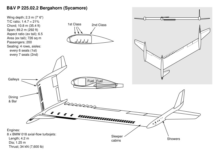
On closer analysis of low-speed manoeuvring characteristics, such as during climbout after takeoff and final approach during landing, it was realised that the .02 revision still had residual control problems.
Wind-tunnel testing revealed that the design would be unsteady in gusty conditions and lacked adequate control for fast, accurate correction without asymmetric Dutch roll and suchlike problems. These would be sufficiently severe as to risk overwhelming the pilot.
B&V were forced to accede that it was necessary to have an arrangement of horizontal control surfaces in two dimensions and not just one, though they remained convinced that the conventional ailerons-plus-elevator was no more than a convention. They instead evolved a triangulated three-control arrangement, by adding a canard foreplane and elevator on the inboard side of the forward nacelle. It was placed high in order to avoid interference with the engine intake airflow. Since it was a lifting surface and larger than the available space, the nose was further lengthened. At the same time a redesign of the nacelle rear re-profiled its upper surface so that it tapered off into a vertical trailing edge in the same manner as the wingtip nacelles, allowing that section to be shortened.
By the end of hostilities and the dissolution of B&V, the -02.2 remained the definitive civil design. When Handley Page later came across a report on the Bergahorn project, they travelled to the US to interview Vogt and Amtmann, leading to their own variable-slew Sycamore project (this report has been my main source of information on the above. I only stumbled on it by accident, as it has been mis-filed by the National Archives and attached to some entirely unrelated documents).
P 226 / BV 41
Meanwhile the bomber had been evolving in a different direction. While work on the civil project continued, the "Amerikabomber" concept had received new impetus. Hitler determined that going back on the offensive was the best form of defence and ordered his current jet aircraft, the Arado Ar 234 reconnaissance plane and the Messerschmitt Me 262 fighter, to be converted respectively to tactical and dive bombing. He still lacked a strategic jet bomber, but while several companies responded to his request for proposals, most also made it clear that their workload was already overpowering and they had no resources for such a large project. One company stood out as an exception. Blohm & Voss had produced some of the largest aeroplanes of the war and these flying boats were now obsolescent. The vast manufacturing facility in Hamburg made the odd prototype of their largest ever flying boat, the BV 235, but was largely kept occupied with stopgap contract work. Their design office had developed a novel and promising approach to jet aircraft, and production could quickly be started.
Hitler was acutely aware of how his command chain had earlier stifled an attempt of his to sanction the BV 237 stuka or dive-bomber intended to replace the ageing Junkers Ju 87, a role which he was now having to shoehorn the unsuitable Me 262 into. So he went over their heads once again, issuing direct orders and funding to B&V. Because of this the aircraft was never given a formal RLM identification, so B&V followed the out-of-sequence numbering originally allocated to the highly secret BV 40 attack glider. This goes some way to explaining the scarcity of official records.
B&V's recommended solution was the P 226 and they returned to it with renewed vigour. A major change from the P 225 was a thinner wing, which now needed to hold only bombs and fuel. The large internal cabin space was no longer necessary, while the drag that it caused reduced both speed and range. The once-planned common structure for the two types was not practicable. With Hitler's order secured, it was designated the BV 41 and disappeared from official records.
BV 42
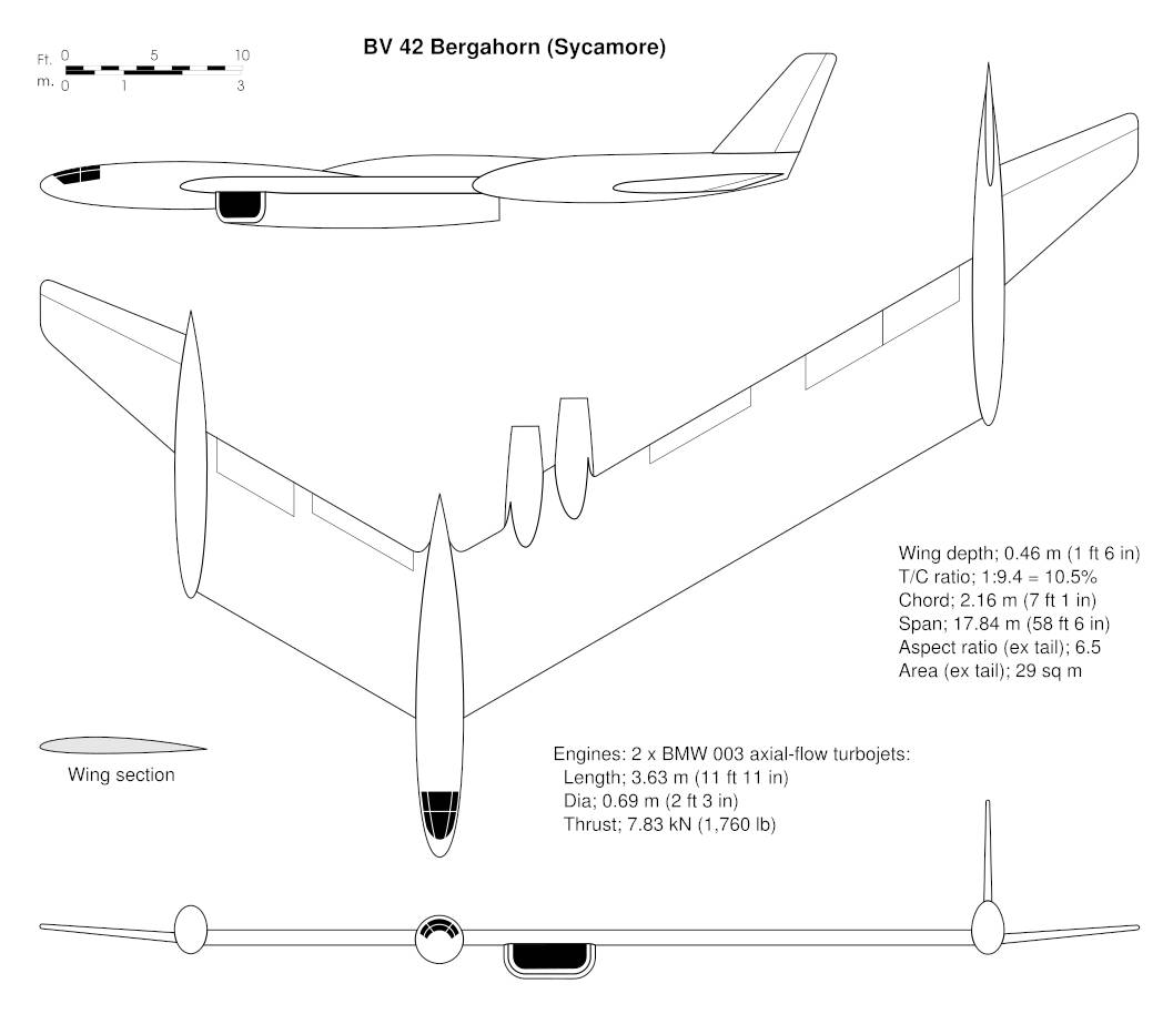
When the British overran Hamburg during the final weeks of the war, they found an experimental prototype aircraft under construction at B&V Finkenwerde. Similar in purpose to the FGP 227 test model for the BV 238, the BV 42 was a 1:5 sub-scale, 17.4 m (58 ft 6 in) span prototype of the BV 41 "Amerikabomber". To minimise the frontal area of the cockpit and avoid excessive aerodynamic effects from non-wing surfaces, the pilot lay in a prone position in the offset fuselage nacelle. Power was to be provided by two BMW 003 axial-flow turbojets, also chosen for their small diameter.
The prototype featured the same tilting wing as the full-size version and it was initially planned for it to be built by Breguet, the French company who were busy finishing off their second BV 144. However secrecy was such that all military work had to be kept in Germany. B&V's landplane work was mostly carried out at their Wenzendorf facility some miles away from their headquarters in Hamburg's Finkenwerde riverside quarter, however Wenzendorf was coming under increasing Allied attack and logistics forced the work to be confined to Finkenwerde, which had miraculously survived the Hamburg firestorm.
In the quest for light weight and use of non-strategic materials, composites such as impregnated plywood and fibre-reinforced resin were being used for non-structural parts and novel tooling was being developed alongside in order to deliver high-volume production. The primary structure was of course B&V's trademark welded sheet steel. Such was Hitler's declared urgency that even some production tooling intended for the new BV 235 was being converted.
So advanced were the concept and calculated performance that the British did not destroy the small workshop but cordoned it off, the other Allies were not informed, and construction was resumed under strict guard. When finished, it was transported to the UK for flight testing. Key staff were brought over with it – some, such as Deputy Chief Designer Hermann Pohlmann, against their will. All documentation and much of the tooling was also taken. The remaining tooling was destroyed, as everything in Finkenwerde would eventually be. (The building survived and was subsequently returned to its owners, the Blohm brothers. Later, Walter Blohm would re-tool it with modern machinery and rebuild his new company, HFB, around it. Today it forms the heart of the German branch of Airbus.)
Back in the UK the prototype was fitted with a pair of prototype Metropolitan-Vickers F.2 engines, chosen because they were the nearest equivalent available to the intended BMW 003. Some redesign of the nacelles was required, as the British engine was a little larger and more powerful. Flight trials confirmed that the basic design was viable, but revealed that some further tuning of the control system would be necessary.
Pohlmann and several other colleagues made it clear that they wished to return to Germany and would not willingly cooperate with any British design project for a full-size craft. Interest from industry proved lukewarm, as they were all busy with their own pet ideas on Britain's first strategic jet bomber, with many of those ideas also coming from captured German research. The decision was made to end the project and destroy the prototype and all records. Any Germans who wished to return home were allowed to only after they had signed secret undertakings never to reveal their visit to Britain. Consequently, there is no mention of the Bergahorn projects in Pohlmann's book about his company, Chronik Eines Flugzeugwerke. However they did manage to smuggle out some of their design sketches and notes, and it is from these that much of the present account has been prepared.
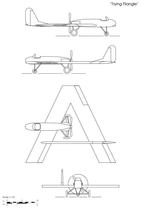
Trying Fliangle
This eccentric machine turned up during one of my trawls through the Science Museum archives. Documentation is minimal and I only found it because it lay in the correspondence folder on one of their exhibits (some over-enthusiastic amateur sleuth had mistakenly ascribed it to the originator of said exhibit). The original documents comprised a photograph of a larger design drawing and a couple of accompanying draft letters, undated and signed only "T".
The designer evidently wanted to prove a point about aerodynamic stability and control. Their correspondent had designed what I assumed at the time to be a simple plank-shaped flying wing. Other researches have since revealed this correspondent to be Otto Kauba and the project in question was the B&V Bergahorn. However Kauba no longer had his Skoda-Kauba works nor access to materials, and was forced to delegate the commission to a UK based designer, the anonymous "T". This sets the date of the design as shortly after the end of WWII. T named it the "Trying Fliangle".
The Fliangle has three control surfaces rather than the two of a typical swept-wing tailless aircraft but, like the more usual type, two of the surfaces have combined action as elevons. In order to obtain data on their relative effectiveness, they are all the same size. Lateral (roll) control is provided by differential action between the right hand surface and the two left hand surfaces acting in unison, with the right hand surface moving twice as far to even up the forces. Pitch control is provided by differential action of the fore and aft left hand surfaces. For example to raise the nose the fore surface is moved down and the rear surface up. The right hand surface is not used for pitch control, as it has no authority about that axis. Thus in a complicated manoeuvre, a left hand surface may be deflected in part for pitch and in part for roll. This doubles the required deflection, meaning that total travel is no different from that of the right hand aileron. It all balances out very neatly and the plane was expected to be docile and controllable in spite of its bizarre asymmetrical form.
To provide stability in pitch the rear wing had three degrees of washout along its span from one tip to the other. No such measure has been taken for lateral stability in roll and I suspect that the designer may not have realised that the forward-swept sections would have introduced an instability which countered the stability created by the rearward-swept sections. Some dihedral should really be added.
A thin boom braces the wings, forming a large stiff triangle with the main spars, and providing a mounting point for the offset tail fin. Unlike say the BV 141, asymmetry in drag is balanced out by offsetting the fuselage slightly to the left. This would introduce its own asymmetry in lift, except that an opposing asymmetry already exists in the washout of the leftmost rear wing, so everything balances nicely once again, with no need of the wasteful side force exerted by the BV 141 tail fin. Span was nominally 25 ft and length 30 ft.
The pusher engine seems to have been a horizontally-opposed flat-four, but whether air- or water-cooled is unclear. This was unusual in the UK at that time, due to the dominance of the de Havilland and Cirrus inline types. Possibly it was a US import, or a prototype of the ill-starred Nuffield.
My drawing is from scratch, based on the photo of the original. It probably has a few mistakes in it, but it gives the general idea.
I cannot say whether the Fliangle was ultimately flown, but I have been able to tentatively identify "T". He may well have been Thieme, the B&V employee who worked up drawing No. Ae607, depicting a radical jet delta flying wing (that many historians assumed to be a hoax until a contemporary copy of the drawing was rediscovered in a major archive collection). Thieme worked in the Advanced Design department under Amtmann and had spent a good deal more time on the Bergahorn projects than his little delta. He came over with the P 42 and, when that project was ended, asked to stay in the UK. To help keep him quiet he was found work with Handley Page. In his new life he hoped to quietly "rediscover" the Bergahorn and interest his employer in it. And indeed, in due course the Bergahorn concept would be developed into Handley Page's more elegant and sophisticated proposal for the "Sycamore" variable-slew asymmetric flying wing airliner, but that too would never see the light of day.
Updated 31 Jan 2023